'Shark Bait Pete'
Starting this blog to help any other amateurs out there build the Joel White 'nutshell pram'. Note I am not a woodworker, or have a trade, but I've made a hobby of woodwork and I've got quite a good few tools.
Dec 2013: looking for something to do next and, after a brief foray into rubber band powered planes , decided to build a small wooden boat for fun, and to eventually get the boys out of the house.
Constraints included a small back yard, small shed, limited side access, and no garage. The boat had to fit in or on the family car (Kia Carnival with builtin roof racks) as I have no room for a caravan. It had to be light enough that two could lift it onto the car roof racks, and not damage the roof racks as well.
2014:
With Google as my friend, I soon found the 7' 7" Nutshell pram and liked Joel White's design as it allowed for a sail, which is pretty cool for a sub 8' dinghy. I bought the plans online and continued to scour youtube for hints while waiting for the plans to arrive.
The plans soon took pride of place on the dining table while I considered my next move, and considered how to build plans given entirely in inches and sixteenths!
LADDER:
I started with the ladder as it was simple and would give me both an appreciation of the size required and a low 'saw horse ' to cut larger sheet material on. Using F7 pine 90x4mm, cut to the plans with a tape measure, square rule, pencil and a cordless Makita circular saw. Fixed together with leftover decking screws , and a cordless driver.
MATERIALS:
Next was a trip to the local marine shops to look at plywood, epoxy, fittings, sails, oars and other exciting stuff! I bought the 1 litre of epoxy and a half litre of hardner with a set of pumps to allow for accurate metering of the glue into a plastic takeaway food container.
Cheap brushes from Mitre10 were bought for use with the epoxy.
I was surprised to find suitable marine grade plywood (8' in length, 2400mm) at Bunnings, and brought the 2 sheets of 6mm, 1 sheet of 9mm and one sheet of 19mm plywood back strapped to the roof rack. Soon that was safely inside the shed, leaning against the wall as flat as I could make it.
BOW AND STERN:
To mark out the plywood for cutting, a great hint is to place the full size paper plans on top of a piece of 19mm ply and push in pins along the curves and at the joints. These pinholes are easy to join with a pencil, and preserves the plans.
After cutting the pieces with a jigsaw, I measured and marked the extent of the bevels.
Placing the cut ply on the 'ladder', I adjusted the bevel angle on the cordless circular saw, and cut by hand and eye! This was nerve wracking first time but actually quit easy due to the low weight and power in the saw.
This gave me the bevelled stern, and bevelled bow, of the dinghy.
WHAT KIND OF WOOD FOR LAMINATIONS?:
I selected a short length of silver ash (1'x1" rough sawn) from Anagote Timbers at Marrickville to make the first laminated piece, the fore keel.
LAMINATED FORE KEEL:
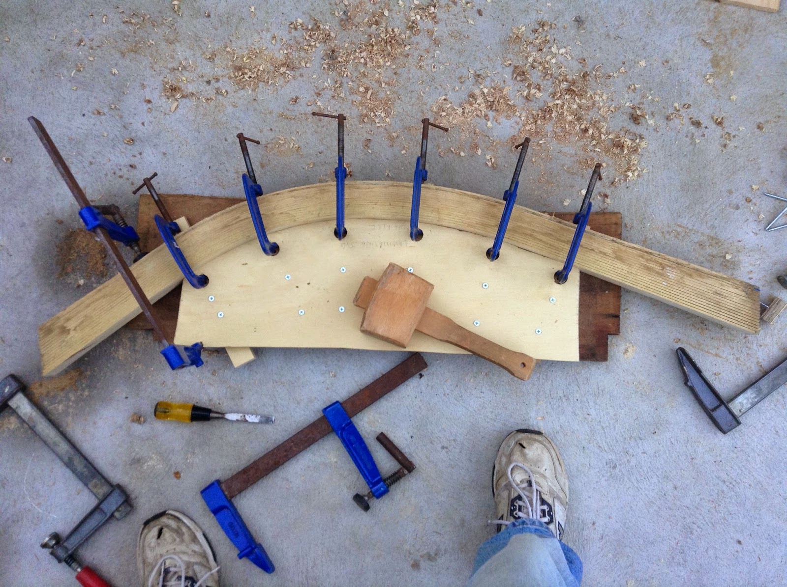
The mound was measured up on 19mm plywood, pushing the pins through the plan, and joining the dots as before. The mould was cut with a jigsaw. To hold the clamps, I used a wide spadebit on a cordless drill to cut holes 1/2" from the front of the mould. That allowed my clamps (small Record G-clamps) to be used along the curve of the mould.
To cut the laminations, I fitted a thin new 8" circular saw blade and played with the fence settings on my Triton workbench until I could rip a 3-3.5 mm lathe off the silver ash. I cut 15 lathes very successfully.
I bent first three, then all 15 dry lathes around the mould to check the clamps and look for problems with the wood or my method.
Next was to line the mould, and my work table with good quality waxed paper (the epoxy will leak straight through the cheap paper), mixed the epoxy, brushed both sides of the lathes and assembled on the mould. Used the Record clamps to pull the laminations tight, used a wooden mallet to gently 'persuade' the laminations to sit square, then poured/brushed more epoxy in for good measure. Pulled off after two days to see that uneven clamping pressure had warped the final result. Used a belt sander to take off the surface epoxy which is quite sharp! Will try to cut it straight on the table saw.
LAMINATED CENTRE RIB:
Making the laminated rib was similar but more care taken. I bought an 8' by 1' by 1" plank of silver ash. With assistance from my youngest, ripping and handling the 8' lathes was quite easy. The lathes are quite springy and easy to bend, and a dry fit trial, bending around two 90* corners on the jig did not break any. So I can thoroughly reccomend the Silver Ash - it is a great timber.
Again with epoxy the laminations are quite slippery and the clamps could not pull around. So I pulled one end by one hand and used the large Record clamps to hold it. Using the smaller clamps to pull the bundle tight against the jig, working from the centre out to the ends. Again before tightening clamps fully, I sloshed in more epoxy with a brush. Left dry for two days. Not much movement when removed from the mould,and again sanded all over with a Makita belt sander. The finished piece looked great, smelled great, and the boys were really surprised how light and strong the finished piece was!
It's been a trouble to work out how to cut the centre laminated rib to the plan - a number of straight cuts that have to be cut accurately on a large and unwieldy shape! I tried to find simple solutions for hours, but eventually just clamped it between two sheets of plywood, using the top piece as an edge for the baseplate of the jigsaw to run along. Of course, I cut it too close, right on the line (duh!) and after sanding flat the laminated rib is now a little too thin - but I don't think it will sink the boat!

After cutting and sanding, I used the jigsaw to make a number of small cuts for the 'limbers' - I'm hoping these are not critical because my accuracy was a bit off - I'm assuming this is just to let the water run along the floor of the boat.

PLYWOOD BOTTOM AND SIDES:
I was going to cut and shape all the smaller pieces of wood next and leave the eventual assembly of the hull until last, but I found that many pieces have few measurements and will have to be trimmed to, and fit against, the final hull assembly.
I looked at the side plank drawings with some trepidation as I had already made some mistakes dealing with the imperial measurements. It is most definitely "measure twice, cut once"!! However, it really turned out to be much simpler than I expected, and I soon had a series of plotted points.
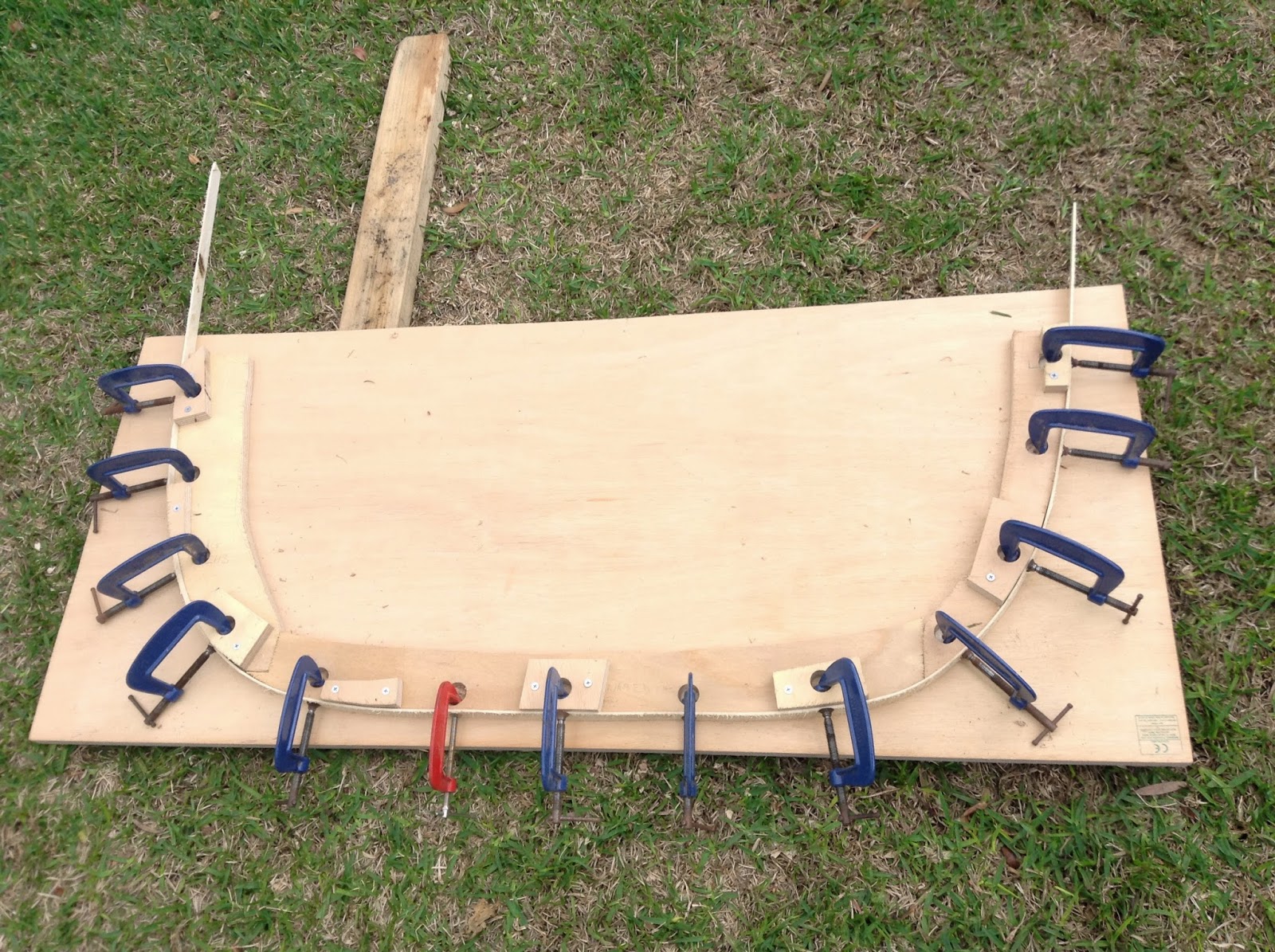
This time I drove small 30mm nails into the plotted points and bent a spare lathe of silver ash against the nails. Errant points, and there were 2 or 3, showed clearly and were quickly re measured ! Running a pencil along the lathe produced very pleasing curves for the three planks on the plan.
Placing the wooden 'ladder' on the lawn, and then two sheets of 6mm plywood on top allowed me to drill a 4mm hole on each empty corner, screw in a 4mm bolt and lock the two 6mm ply pieces together. Then I run a jigsaw along the pencil lines to produce both left and right sides of the dinghy (the garboard plank, centre plank, and sheer plank).
The cut pieces were carefully stacked flat on shelving to prevent warping.
Cutting temporary bulkheads:
these were marked out with pins and the pin holes joined with pencil lines as the other moulds, using 3/4" plywood left over from making the bow and stern transoms.
ASSEMBLY:
finally got to start putting it all together - a little worried that the string line isn't dead centre down each of the moulds, but we'll see what affect that has on pulling the plywood sides down to the moulds later. (found out later it was quite important - resulted in rework!!)
From left to right, the bow and forekeel, stage 1 temporary mould, stage 2 laminated centre rib, stage 3 temporary mould, and stern transom.
 Because the brass screws exited the transom, I used an angle grinder to grind them flat on the inside and on the outside


